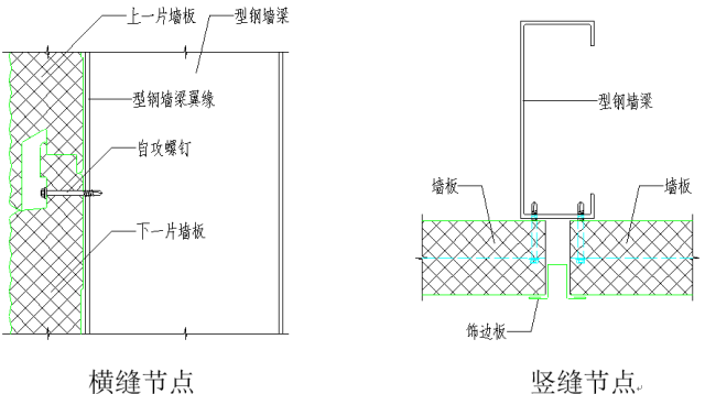
1. Architecture system
1-1. Portal frame system
1-1-1. Basic component diagram
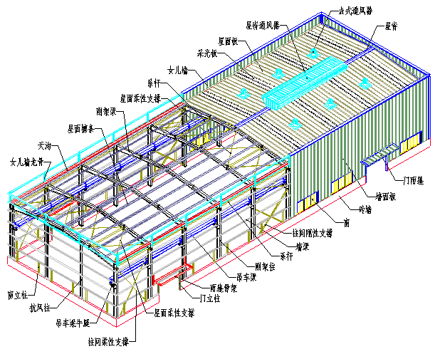
1-1-2. Description
Principle of mechanics
Portal frame structure is mainly stressed by transverse rigid frame composed of columns and beams, and the rigid frame is a plane stressed system. In order to ensure longitudinal stability, inter column support and roof support are set.
rigid frame
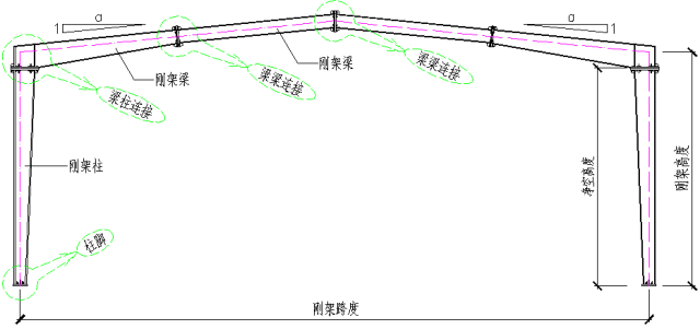
Rigid frame columns and beams are made of section H-shaped steel, and various loads are transmitted to the foundation through columns and beams.
Support and tie rod
The rigid support is made of hot-rolled section steel, generally angle steel. The flexible support is round steel. The tie rod is a compressed circular steel pipe, which forms a stress closed system with the support.
Roof purlin and wall beam
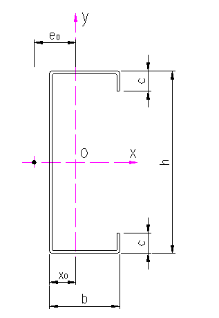
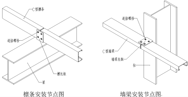
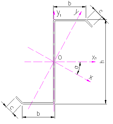
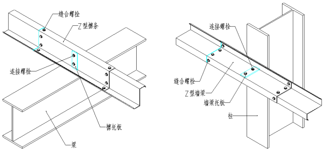
Generally C-section steel and Z-section steel. Bear the force transmitted from roof panel and wall panel, and transmit the force to columns and beams.
1-1-3. Basic form of portal frame
a. Typical portal frame
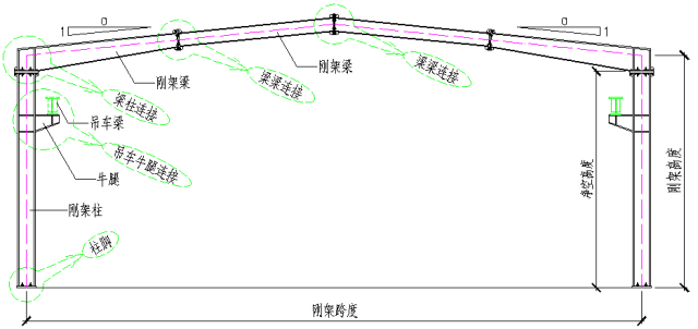
b. Portal frame with crane
c. Portal frame with partial second floor
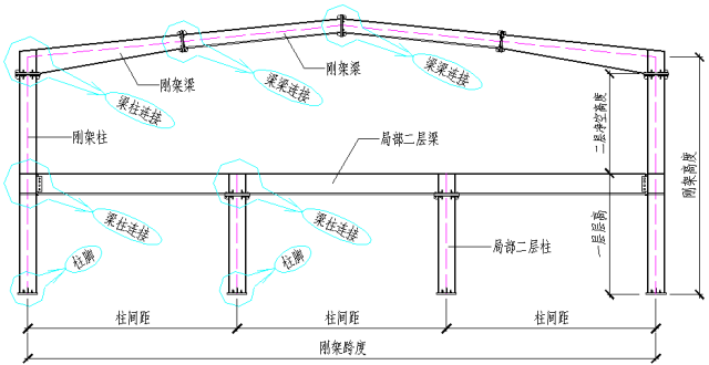
1-1-4. Basic nodes
a. Column base joint
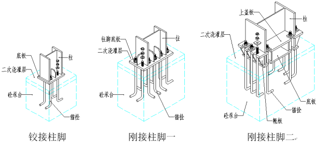
b. Beam and column joints
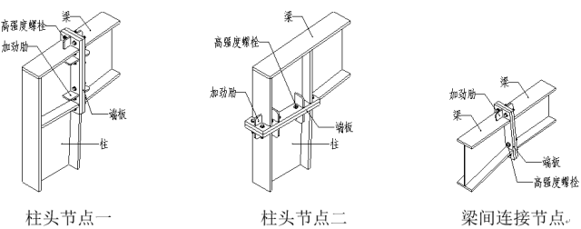
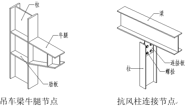
■ local second floor nodes refer to multi-storey frame system.
1-1-5. Derived form of rigid frame
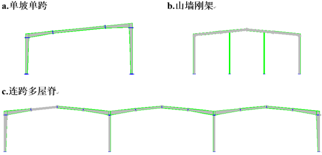
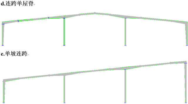
■ the crane and partial second floor can be arranged in the derived form of rigid frame.
■ gable rigid frame is also a multi span rigid frame in essence, but the middle column and rigid frame column rotate 90 degrees compared with the section.
1-2. Multi layer frame system
1-2-1. Frame diagram
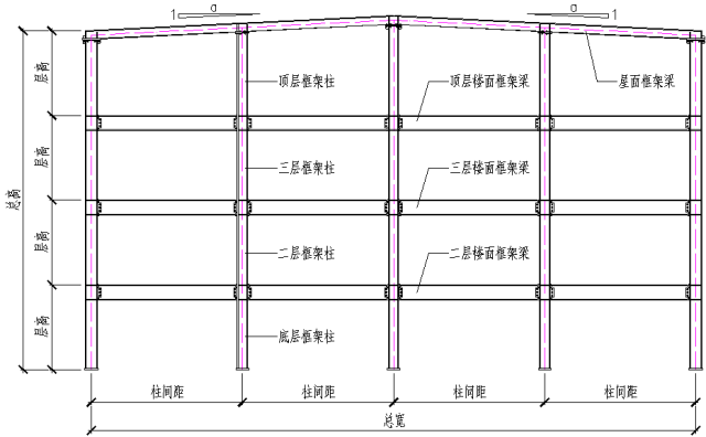
1-2-2. Description
mechanical model
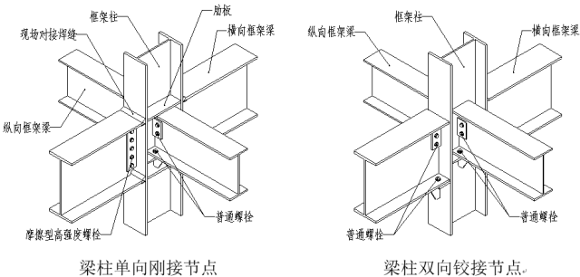
a. Pure rigid frame: rigid frame is adopted in both vertical and horizontal directions.
b. Rigid connection - supporting frame: rigid connection is adopted in the transverse direction, hinged connection is adopted in the longitudinal direction, and support is set in the longitudinal direction to transmit horizontal force.
c..Braced frame: hinged is adopted in both vertical and horizontal directions, and supports are set in both directions to transmit horizontal force.
d. Sometimes, in order to ensure sufficient stiffness, supports are also set in the rigid frame.
Frame column
The frame column can adopt H-shaped section, box section, cross section, circular tubular section, etc. All superstructure forces are transmitted to the foundation through frame columns.
Frame beam
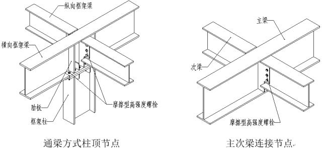
The frame beam generally adopts H-shaped section. The force on the floor and roof is transmitted to the frame column through the frame beam.
brace
The support is generally made of hot-rolled section steel, and its function is to transfer the horizontal force between layers and ensure the stiffness of the structure.
1-2-3. Basic nodes
a. Column base joint
■ the column base node is the same as the portal frame system.
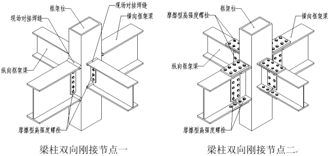
b. Column and beam joints
2. Support and tie rod
2-1. Diagram
Flexible support between columns rigid support between columns
2-2. Description
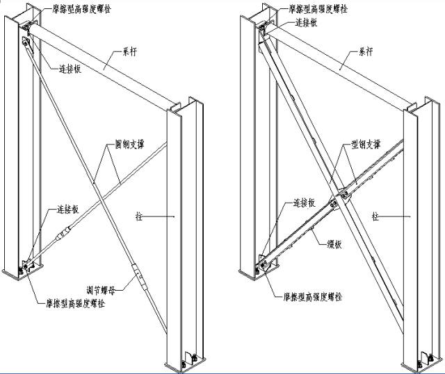
■ support is divided into flexible support and rigid support. The flexible support is made of round steel and must be tensioned during installation. It is mainly used for portal frame structure. The rigid support is made of section steel and is used in structures with high stiffness requirements such as multi-storey frame and lower section support of crane beam.
■ tie rod and support work together to form a closed stress system. When there are rigid members at the support end and transmit pressure, it is not necessary to set tie rods.
■ the method of roof horizontal support is the same as that between columns.
■ according to the needs, the support can also be herringbone, splay, K-shaped, V-shaped, door shaped, L-shaped, Y-shaped, single inclined rod and other forms.
3. Corner brace
3-1. Diagram
3-2. Description
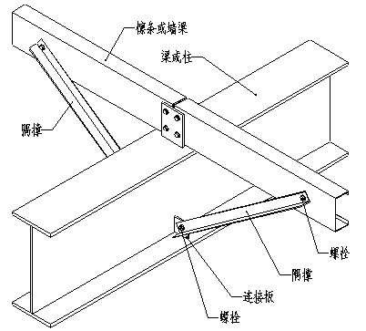
■ the setting of the corner brace is based on the out of plane calculated length of the compression flange of the beam or column. The corner brace can be made of angle steel or pressed by flat steel.
■ in multi-storey frame system, horizontal corner brace is often set at the position of beam column rigid connection.
4. Crane beam
4-1. Diagram
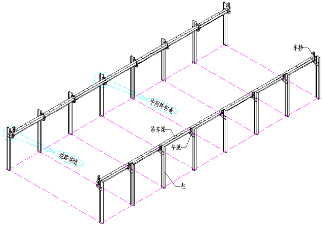
Crane beam side span structure
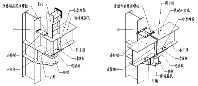
Middle span structure of crane beam
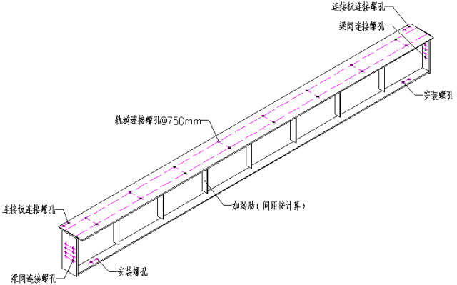
Standard crane beam drawing
4-1. Description
■ the crane beam is the load-bearing member of the crane, which is welded by steel plate.
■ refer to the side span structure for the treatment of deformation joint position.
■ when the crane tonnage is large, set the brake truss or brake beam to resist the transverse horizontal load.
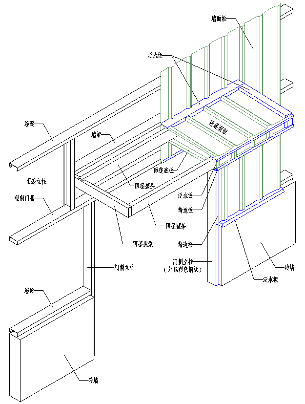
The profiled steel plate for canopy adopts hv-197td-788 plate and hv-205td-820 plate.
6. Purlin, wall beam
6-1. C-shaped cold-formed thin-walled section steel
6-1-1 section characteristics of section steel
6-1-2. Installation node diagram
6-2. Z-shaped cold-formed thin-walled section steel
6-2-1 section characteristics of section steel
6-2-2. Installation node diagram
通用领域生物医药
7. Profiled steel sheet for roof and wall
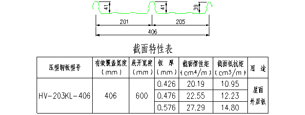
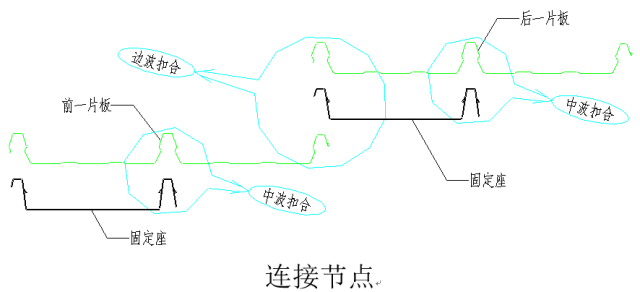
7-1. Hv-203kl-406 plate
7-1-1. Plate type diagram
7-1-2. Connection node diagram

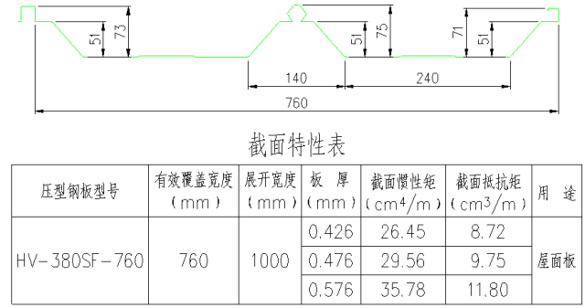
7-2、HV-380SF-760
7-2-1 plate type diagram
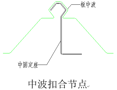
7-2-2. Connection node diagram

7-3. Hv-475sf-475 plate
7-3-1 plate type diagram
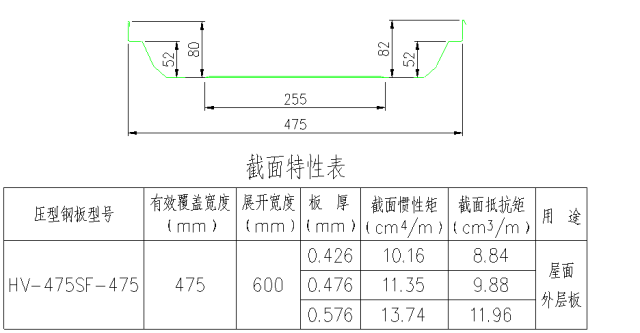
7-3-2. Connection node diagram

7-4. Hv-197td-788 plate
7-4-1 plate type diagram
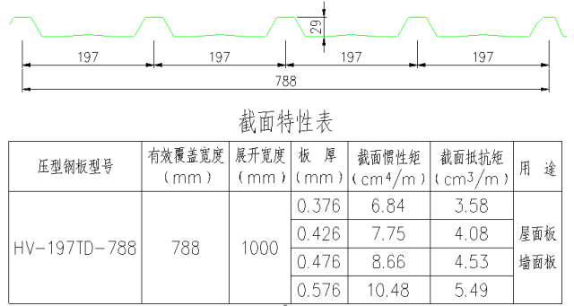
7-4-2. Connection node
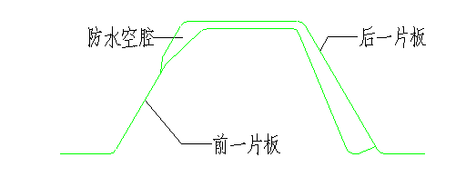
explain:
■ waterproof cavity can prevent water seepage caused by capillarity.
■ this plate type can be used for roof panel and wall panel, and is connected with roof purlin or wall beam by self tapping screws.
■ when used as roof panel, the screw passes through the wave crest and is fixed with the roof purlin; When used as a wall panel, the screw is fixed with the wall beam in the straight section of the wave trough close to the wave crest.
7-4. Hv-205td-820 plate
7-5-1 plate type diagram
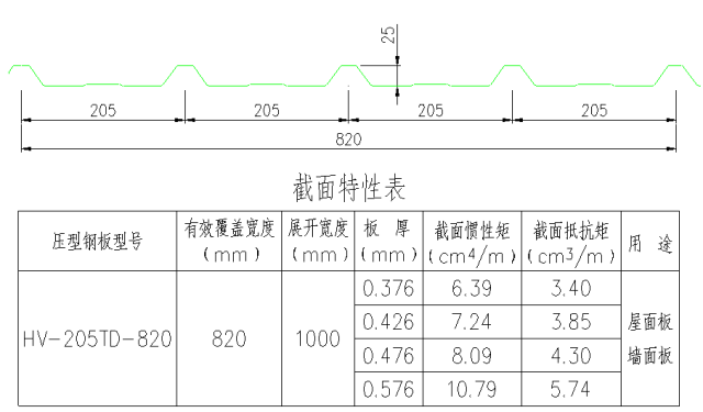
7-5-2. Connection node diagram
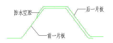
explain:
■ waterproof cavity can prevent water seepage caused by capillarity.
■ this plate type can be used for roof panel and wall panel, and is connected with roof purlin or wall beam by self tapping screws.
■ when used as roof panel, the screw passes through the wave crest and is fixed with the roof purlin; When used as a wall panel, the screw is fixed with the wall beam in the straight section of the wave trough close to the wave crest.
7-6. Hv-225td-900 plate
7-6-1 plate type diagram
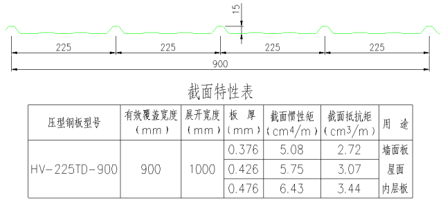
7-6-2. Connection node diagram
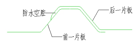
explain:
■ waterproof cavity can prevent water seepage caused by capillarity.
■ this plate type is used for wall panel and is connected with roof purlin or wall beam by self tapping screws; The screw is fixed with the wall beam at the straight section of the wave trough near the wave crest.
7-7. Hv-360yc-360 plate
7-7-1 plate type diagram
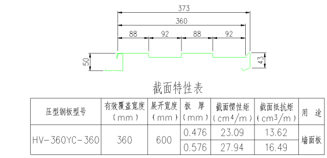
7-7-2. Connection node diagram
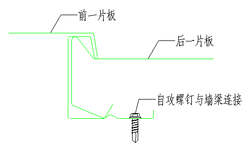
explain:
■ the self tapping screw passes through the plate and is directly connected with the wall beam.
7-8. Hv-300yc-300 plate
7-8-1 plate type diagram
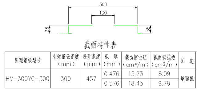
7-8-2. Connection node diagram
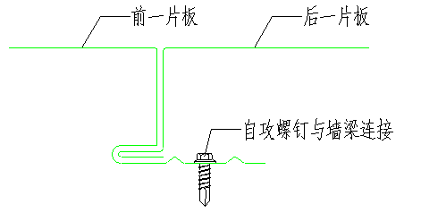
explain:
■ the self tapping screw passes through the plate and is directly connected with the wall beam.
7-9. Hv-1000hp-1000 plate
7-9-1 plate type diagram

7-9-2. Connection node diagram
